How to Insert Components into a Schematic in Autodesk Electrical
Inserting components into a schematic drawing in Autodesk Electrical is a foundational step in the electrical design process. Whether you’re designing a simple circuit or a complex system, accurately placing components is crucial for creating a clear and functional schematic. In this comprehensive guide, we’ll explore the various methods and best practices for inserting components into a schematic drawing in Autodesk Electrical, ensuring efficiency, accuracy, and clarity in your designs.
1. Understanding Component Insertion in Autodesk Electrical
Before diving into the insertion process, it’s essential to understand how component insertion works in Autodesk Electrical.
Component Libraries
- Standard Libraries: Autodesk Electrical provides a comprehensive set of standard component libraries covering a wide range of electrical components.
- Custom Libraries: Users can create custom component libraries to accommodate specific project requirements or proprietary components.
Component Properties
- Tags and Descriptions: Each component in Autodesk Electrical has associated tags and descriptions that provide essential information about the component.
- Catalog Information: Components may include catalog information such as manufacturer part numbers and specifications.
2. Accessing Component Libraries
To begin inserting components into a schematic, you’ll need to access the component libraries within Autodesk Electrical.
Step 1: Open Component Library Manager
- Main Toolbar: Locate and click on the Component Library Manager icon in the main toolbar of Autodesk Electrical.
- Library Selection: Choose the appropriate component library from the available options, such as IEC, ANSI, or custom libraries.
Step 2: Browse Component Categories
- Library Structure: Navigate through the component library structure to locate the desired category of components.
- Subcategories: Drill down into subcategories to narrow down the search for specific types of components.
3. Inserting Components Using the Icon Menu
The Icon Menu provides a quick and intuitive way to insert components directly into your schematic drawing.
Step 3: Open Icon Menu
- Icon Menu Button: Click on the Icon Menu button located in the toolbar at the top of the Autodesk Electrical interface.
- Select Component: Browse through the list of available component icons and select the desired component to insert.
Step 4: Place Component in Drawing
- Click to Place: Click on the drawing canvas to place the selected component at the desired location.
- Drag and Drop: Alternatively, you can drag the component icon from the Icon Menu directly onto the drawing canvas to place it.
4. Inserting Components Using the Component Browser
The Component Browser offers a more comprehensive search and selection interface for inserting components.
Step 5: Open Component Browser
- Component Browser Button: Click on the Component Browser button located in the toolbar.
- Search Components: Use the search bar to enter keywords or component codes to quickly locate specific components.
Step 6: Select and Place Component
- Select Component: Click on the desired component from the search results to select it.
- Place Component: Click on the drawing canvas to place the selected component at the desired location.
5. Configuring Component Properties
After inserting components into your schematic, it’s essential to configure their properties to accurately represent the electrical system.
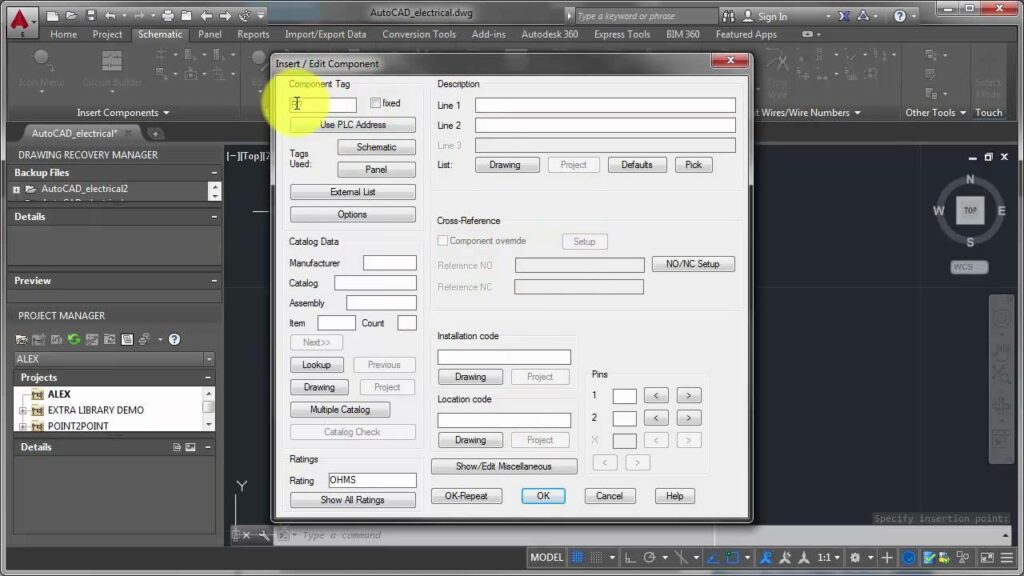
Step 7: Edit Component Properties
- Select Component: Click on the inserted component to select it.
- Edit Properties: Right-click on the component and choose the ‘Properties’ option to access its properties dialog box.
Step 8: Configure Tags and Descriptions
- Tags: Assign a unique tag to the component to identify it within the schematic.
- Descriptions: Provide a detailed description of the component’s function or purpose.
Step 9: Specify Catalog Information
- Catalog Numbers: Enter any relevant catalog information, such as manufacturer part numbers or specifications.
- Datasheets: Attach datasheets or documentation files to provide additional information about the component.
6. Inserting Multi-Part Components
Some components, such as relays or connectors, consist of multiple parts that need to be inserted together.
Step 10: Select Multi-Part Component
- Identify Component: Locate the multi-part component in the component library.
- Insert All Parts: Insert all parts of the multi-part component simultaneously to ensure proper alignment.
Step 11: Arrange and Connect Parts
- Arrange Parts: Position the individual parts of the multi-part component in the desired configuration on the drawing canvas.
- Connect Parts: Use wires or connection lines to connect the various parts of the component as needed.
7. Inserting Custom Components
In addition to standard components, Autodesk Electrical allows users to create and insert custom components.
Step 12: Create Custom Component
- Custom Component Editor: Access the Custom Component Editor from the main toolbar.
- Design Component: Design the custom component by specifying its geometry, properties, and connections.
Step 13: Insert Custom Component
- Component Library: Save the custom component to a custom component library for future use.
- Insertion Process: Insert the custom component into the schematic using the same methods described earlier for standard components.
8. Best Practices for Component Insertion
Following best practices can help ensure accuracy and efficiency when inserting components into a schematic.
Standardize Naming Conventions
- Consistent Tags: Use a consistent tagging system for components to maintain clarity and organization within the schematic.
- Descriptive Descriptions: Provide clear and descriptive descriptions for components to convey their function or purpose effectively.
Utilize Library Management Features
- Custom Libraries: Create custom component libraries to organize and manage proprietary or project-specific components.
- Favorites: Use the Favorites feature to bookmark frequently used components for quick access.
Check for Updates and Revisions
- Regular Updates: Periodically review and update component libraries to incorporate new components or revisions.
- Revision Control: Implement a revision control system to track changes and updates to component libraries.
Collaborate and Share Knowledge
- Team Collaboration: Foster collaboration among team members to share knowledge and expertise in component selection and usage.
- Documentation: Document component selections and usage guidelines to ensure consistency and facilitate knowledge sharing.
Conclusion
Inserting components into a schematic drawing in Autodesk Electrical is a fundamental aspect of electrical design. By following the steps outlined in this guide and adhering to best practices, you can ensure accuracy, efficiency, and clarity in your schematic designs. Whether you’re working on simple circuits or complex systems, mastering the component insertion process will enable you to create high-quality schematics that meet your project requirements effectively. Happy designing!