How to Create a New Schematic Drawing in Autodesk Electrical

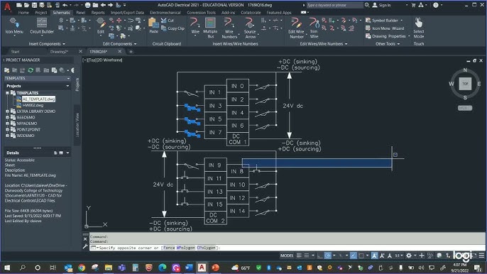
Creating a new schematic drawing in Autodesk Electrical is a fundamental skill for electrical engineers and designers. A well-constructed schematic not only facilitates the accurate representation of electrical systems but also ensures clarity, consistency, and efficiency in design. This comprehensive guide will take you through every step of the process, from initial setup to final adjustments, providing detailed instructions and best practices to help you create high-quality schematic drawings in Autodesk Electrical.
1. Preparing for a New Schematic Drawing
Before starting a new schematic drawing, it’s essential to prepare your Autodesk Electrical environment and gather the necessary resources.
Check System Requirements
- System Compatibility: Ensure your computer meets the requirements for running Autodesk Electrical, including sufficient RAM, disk space, and a compatible operating system.
- Software Version: Verify that you are using the latest version of Autodesk Electrical to take advantage of the newest features and updates.
Gather Resources
- Component Libraries: Ensure you have access to the necessary component libraries and symbols.
- Reference Materials: Gather any reference materials, such as design specifications, component datasheets, and wiring diagrams.
Backup Existing Data
- Backup Projects: Backup any existing projects that may be referenced or modified during the drawing process.
- Backup Settings: Backup your Autodesk Electrical settings to avoid data loss.
2. Setting Up a New Project
Creating a new schematic drawing typically starts with setting up a new project. This project will serve as the container for your schematic drawings and related files.
Step 1: Launch Autodesk Electrical
- Open Autodesk Electrical: Start by launching Autodesk Electrical from your desktop or start menu.
- Welcome Screen: From the welcome screen, you can create a new project or access existing projects.
Step 2: Create a New Project
- Open Project Manager: Click on the ‘Project Manager’ icon from the main toolbar to open the Project Manager window.
- New Project Button: Click on the ‘New Project’ button.
- Project Name and Location: Enter a name for your new project and specify the location where the project files will be saved.
Step 3: Configure Project Properties
- General Settings: Enter the project description, project number, and any other relevant details in the Project Properties window.
- Electrical Standards: Set the default electrical standards (e.g., IEC, ANSI) for the project.
- Drawing Format: Specify the default drawing format, including sheet size, title block, and border.
3. Creating a New Schematic Drawing
With the project set up, you can now create a new schematic drawing.
Step 4: Open the Project
- Open Project: In the Project Manager, double-click on the project name to open it.
- Project Explorer: Use the Project Explorer to navigate through your project files.
Step 5: Create a New Drawing
- New Drawing Button: Click on the ‘New Drawing’ button in the Project Manager.
- Drawing Name and Location: Enter a name for your new drawing and specify the location within the project folder.
Step 6: Configure Drawing Properties
- Drawing Properties: Right-click on the new drawing name in the Project Manager and select ‘Properties’.
- Title Block and Border: Set up the title block and border according to your organization’s standards.
- Layers: Configure the layers you will use in the drawing, including layers for wires, components, and annotations.
4. Adding Components to the Schematic
With your drawing setup, the next step is to add electrical components to the schematic.
Step 7: Open the Component Library
- Component Library Manager: Access the Component Library Manager from the main toolbar.
- Select Components: Browse through the component libraries to select the components you need for your schematic.
Step 8: Insert Components
- Insert Tool: Use the Insert Component tool from the toolbar to place components on the drawing.
- Component Properties: Configure the properties for each component, including tags, descriptions, and catalog numbers.
- Place Components: Click on the drawing to place the components in their appropriate locations.
5. Connecting Components with Wires
After placing the components, the next step is to connect them with wires.
Step 9: Select Wire Type
- Wire Type Manager: Open the Wire Type Manager from the main toolbar.
- Choose Wire Type: Select the wire type you will use for the connections, configuring properties such as color, gauge, and layer.
Step 10: Draw Wires
- Draw Wire Tool: Use the Draw Wire tool from the toolbar.
- Connect Components: Click on the start point of the connection, drag the wire to the end point, and click again to finish the connection.
Step 11: Configure Wire Properties
- Wire Properties: Right-click on each wire to configure its properties, including tags and descriptions.
- Wire Numbering: Use the automatic wire numbering feature to assign numbers to each wire.
6. Annotating the Schematic
Annotations help clarify the schematic and provide additional information about the components and connections.
Step 12: Add Text Annotations
- Text Tool: Use the Text tool from the toolbar to add annotations to the drawing.
- Text Properties: Configure the text properties, including font, size, and layer.
Step 13: Add Labels and Tags
- Label Tool: Use the Label tool to add labels and tags to components and wires.
- Label Properties: Configure the label properties to ensure clarity and consistency.
Step 14: Add Reference Numbers
- Reference Tool: Use the Reference tool to add reference numbers to components and wires.
- Reference Properties: Configure the reference properties, including format and placement.
7. Cross-Referencing and Error Checking
Cross-referencing and error checking are critical steps to ensure the accuracy and completeness of your schematic.
Step 15: Cross-Reference Components
- Cross-Reference Tool: Use the Cross-Reference tool from the toolbar to link related components across different drawings.
- Cross-Reference Settings: Configure the cross-reference settings to match your project standards.
Step 16: Perform Error Checking
- Error Checking Tool: Use the Error Checking tool to identify and resolve issues in your schematic.
- Review Errors: Review the list of errors and make necessary corrections.
8. Finalizing the Schematic Drawing
Once you have added and connected all components, it’s time to finalize the schematic drawing.
Step 17: Review the Drawing
- Visual Inspection: Conduct a visual inspection of the drawing to ensure all components are placed correctly and all connections are made.
- Check Annotations: Verify that all annotations, labels, and tags are correct and clear.
Step 18: Generate Reports
- Report Manager: Open the Report Manager from the main toolbar.
- Generate BOM: Generate a Bill of Materials (BOM) for the schematic.
- Generate Wiring List: Generate a wiring list for the schematic.
Step 19: Save and Backup the Drawing
- Save Drawing: Save the schematic drawing in the project folder.
- Create Backup: Create a backup of the drawing to prevent data loss.
9. Printing and Sharing the Schematic
After finalizing the schematic, you may need to print or share it with team members or clients.
Step 20: Print the Drawing
- Print Setup: Configure the print settings, including paper size, orientation, and scale.
- Print Preview: Use the Print Preview tool to check the layout before printing.
- Print: Print the schematic drawing.
Step 21: Share the Drawing
- Export Drawing: Export the drawing in a suitable format, such as PDF or DWG, for sharing.
- Cloud Storage: Use cloud storage services like Autodesk Drive or other third-party services to share the drawing files.
- Email: Email the drawing files to team members or clients as needed.
10. Best Practices for Creating Schematic Drawings
Following best practices can help you create high-quality schematic drawings more efficiently.
Standardize Procedures
- Standard Operating Procedures (SOPs): Develop and document SOPs for creating schematic drawings.
- Templates: Use drawing templates to maintain consistency and save time.
Regular Backups
- Backup Schedule: Schedule regular backups of your project files to prevent data loss.
- Backup Procedures: Document backup procedures to ensure all team members know how to create and restore backups.
Continuous Improvement
- Stay Updated: Stay informed about new features and updates in Autodesk Electrical.
- Feedback Loop: Establish a feedback loop with team members to gather suggestions for improving schematic drawings.
Training and Development
- Training Programs: Provide regular training for your team on Autodesk Electrical and schematic drawing best practices.
- Skills Development: Encourage team members to develop their skills and stay updated with industry trends.
Conclusion
Creating a new schematic drawing in Autodesk Electrical is a detailed process that requires careful planning, execution, and review. By following this comprehensive guide, you can create high-quality schematic drawings that are accurate, consistent, and efficient. Regularly updating your skills and staying informed about best practices in Autodesk Electrical will further enhance your ability to create and manage schematic drawings effectively. Happy designing!


