Mastering Mold Tool Design in SolidWorks: A Comprehensive Guide
Introduction: Designing mold tools is a crucial aspect of the manufacturing process, especially in industries such as automotive, aerospace, consumer goods, and electronics. SolidWorks, a leading 3D CAD software, provides powerful tools and functionalities for creating intricate mold tool designs with precision and efficiency. In this comprehensive guide, we will explore the fundamental principles, best practices, and advanced techniques for designing mold tools in SolidWorks, covering everything from initial concept development to final mold assembly.
Section 1: Understanding Mold Tool Design
1.1 Overview of Mold Tools: Mold tools, also known as molds or dies, are specialized tools used in manufacturing processes to shape raw materials into desired forms. They are commonly used in injection molding, compression molding, and die casting processes to produce plastic, metal, or composite components with high precision and repeatability.
1.2 Types of Mold Tools: Mold tools come in various types, including:
- Injection Molds: Used in injection molding processes to produce complex plastic components by injecting molten material into a mold cavity.
- Compression Molds: Employed in compression molding processes to shape materials by applying pressure and heat to a mold cavity.
- Die Casting Dies: Utilized in die casting processes to produce metal components by injecting molten metal into a mold cavity under high pressure.
1.3 Key Considerations in Mold Tool Design: Designing mold tools requires careful consideration of factors such as part geometry, material properties, manufacturing constraints, tooling costs, and production volumes. SolidWorks provides tools and features to address these considerations and streamline the mold tool design process effectively.
Section 2: Mold Tool Design Workflow
2.1 Concept Development: The mold tool design process typically begins with concept development, where designers brainstorm ideas, sketch initial concepts, and define design requirements based on customer specifications, part geometry, and production constraints. SolidWorks’ sketching tools, design libraries, and 3D modeling capabilities facilitate concept exploration and visualization.
2.2 Part Modeling: Once the concept is finalized, designers use SolidWorks to create detailed 3D models of the mold tool components, including the mold base, cavity, core, inserts, ejector pins, cooling channels, and other features. SolidWorks’ parametric modeling capabilities enable designers to iterate on part geometry, dimensions, and features efficiently.
2.3 Assembly Design: Assembling mold tool components into a complete mold assembly is a critical step in the design process. SolidWorks’ assembly design tools allow designers to mate, align, and arrange components within the mold assembly, ensuring proper fit, clearance, and functionality. Virtual assembly simulations help identify interferences, clashes, and assembly errors early in the design process.
2.4 Detailing and Documentation: Generating detailed drawings and documentation is essential for communicating design intent, manufacturing specifications, and quality requirements to toolmakers and manufacturers. SolidWorks’ drawing tools enable designers to create dimensioned drawings, bill of materials (BOM), assembly instructions, and other documentation necessary for mold tool fabrication and assembly.
Section 3: Mold Tool Design Features and Techniques
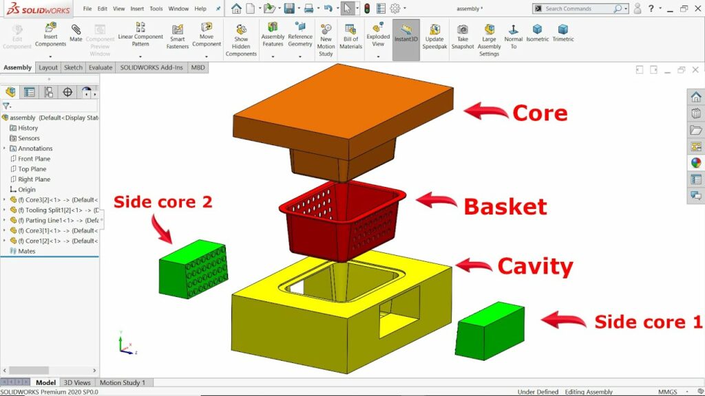
3.1 Core and Cavity Design: Designing the core and cavity components is a critical aspect of mold tool design. SolidWorks provides specialized features such as the Parting Line tool, Draft Analysis tool, and Cavity tool to create core and cavity components accurately and efficiently. Designers can also use split features, surface modeling, and cavity inserts to accommodate complex part geometries and undercuts.
3.2 Mold Base Design: The mold base provides the foundation and support structure for mold tool components. SolidWorks offers standard mold base libraries and customizable mold base components to streamline mold base design. Designers can configure mold base parameters, select standard components, and customize features such as cooling channels, runner systems, and alignment mechanisms.
3.3 Cooling System Design: Efficient cooling is essential for maintaining uniform temperatures and minimizing cycle times in mold tooling processes. SolidWorks’ integrated mold design features enable designers to create cooling channels, baffles, and inserts within mold tool components. Thermal analysis tools help optimize cooling system design for improved part quality and productivity.
3.4 Draft Analysis and Undercut Detection: Draft analysis tools in SolidWorks enable designers to assess part geometry for draft angles, undercuts, and manufacturability constraints. By analyzing parting lines and identifying areas requiring draft, designers can optimize part geometry for moldability and facilitate demolding during production.
Section 4: Advanced Techniques and Applications
4.1 Mold Flow Analysis: Mold flow analysis software, integrated with SolidWorks, enables designers to simulate the filling, packing, and cooling stages of injection molding processes. By analyzing flow patterns, pressure distributions, and temperature gradients, designers can optimize mold tool design, gate locations, and processing parameters to minimize defects and improve part quality.
4.2 Mold Tool Optimization: SolidWorks’ parametric modeling capabilities and simulation tools facilitate mold tool optimization for performance, cost, and manufacturability. Designers can use parametric studies, design optimization tools, and finite element analysis (FEA) to refine mold tool geometry, enhance structural integrity, and reduce material usage while maintaining design requirements.
4.3 Overmolding and Insert Molding: Overmolding and insert molding are specialized molding techniques used to encapsulate inserts, inserts, or secondary components within a primary molded part. SolidWorks provides tools for designing mold tooling for overmolding and insert molding processes, including cavity inserts, mold inserts, and overmolding features.
Section 5: Best Practices and Tips
5.1 Collaboration and Communication: Effective collaboration and communication between designers, toolmakers, and manufacturers are essential for successful mold tool design projects. SolidWorks’ collaboration tools, including PDM (Product Data Management) systems and cloud-based collaboration platforms, facilitate real-time communication, version control, and data sharing among stakeholders.
5.2 Design for Manufacturing (DFM): Designing mold tools with manufacturability in mind is crucial for minimizing tooling costs, reducing lead times, and ensuring quality production. Designers should follow design for manufacturing (DFM) principles, such as simplifying part geometry, minimizing tooling complexity, and optimizing material selection, to streamline the mold tool design process and enhance manufacturability.
5.3 Continuous Learning and Professional Development: Mold tool design is a complex and evolving field that requires continuous learning and professional development. Designers should stay updated on the latest SolidWorks features, mold design methodologies, and industry trends through training, certification programs, and participation in professional organizations and conferences.
Conclusion: Designing mold tools in SolidWorks offers engineers and designers a versatile and efficient platform for creating high-quality molds for various manufacturing processes. By mastering the fundamental principles, design techniques, and best practices discussed in this guide, designers can tackle complex mold tool design challenges with confidence and precision. With SolidWorks’ robust modeling capabilities, simulation tools, and collaborative features, engineers can optimize mold tool designs, accelerate product development cycles, and drive innovation in manufacturing industries.