Mastering Fillets in SolidWorks: A Comprehensive Guide
Introduction: SolidWorks, a leading computer-aided design (CAD) software, empowers engineers and designers to create precise and intricate 3D models for a wide range of industries. Among its array of features, fillets stand out as essential tools for adding rounded edges and smooth transitions to parts, enhancing both aesthetics and functionality. In this extensive guide, we’ll explore the intricacies of creating fillets in SolidWorks, covering fundamental concepts, essential techniques, and advanced strategies to help you master this versatile tool.
Understanding Fillets in SolidWorks: Fillets in SolidWorks are features that round or chamfer edges and corners of parts, creating smooth transitions between adjacent surfaces. Fillets serve various purposes, including improving part durability, reducing stress concentrations, and enhancing visual appeal. Before delving into the specifics of creating fillets, it’s crucial to grasp some foundational concepts:
- Sketching:
- Sketching forms the basis of design in SolidWorks, allowing users to create 2D profiles that define the geometry of parts and features. Sketch entities such as lines, arcs, circles, and splines are used to create sketch geometry.
- Fillet Feature:
- The Fillet feature in SolidWorks enables users to add rounded or chamfered edges to parts. Users can specify parameters such as radius, face selection, and fillet type (constant radius or variable radius) to customize the fillet geometry.
- Chamfer Feature:
- The Chamfer feature is similar to the Fillet feature but creates beveled edges instead of rounded edges. Chamfers are typically used for aesthetic purposes or to facilitate assembly by providing clearance between mating components.
Creating Fillets in SolidWorks: SolidWorks offers multiple methods for creating fillets, each suited to different design requirements and preferences. Let’s explore the essential tools and techniques for generating fillets:
- Fillet Feature:
- The Fillet feature is the primary method for adding rounded edges to parts in SolidWorks. Users can access the Fillet feature from the Features tab and select the edges or corners to be filleted. SolidWorks then applies the specified radius to create the fillet.
- Chamfer Feature:
- While not strictly a fillet, the Chamfer feature is another option for creating smooth transitions between edges. Users can access the Chamfer feature from the Features tab and specify parameters such as distance and angle to create beveled edges.
- FilletXpert:
- FilletXpert is a tool in SolidWorks that automates the process of creating fillets by analyzing the part geometry and suggesting suitable fillet sizes and configurations. Users can access FilletXpert from the Fillet PropertyManager and adjust parameters as needed.
Advanced Filleting Techniques: In addition to basic filleting tools, SolidWorks offers advanced techniques to enhance fillet creation workflows and achieve complex design objectives:
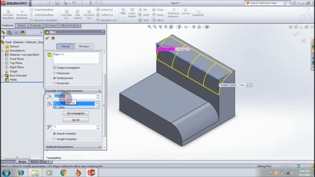
- Variable Radius Fillets:
- SolidWorks allows users to create fillets with varying radii along a single edge or between multiple edges. Variable radius fillets are useful for creating smooth transitions and controlling stress concentrations in parts with complex geometry.
- Tangent Propagation:
- Tangent propagation is a feature in SolidWorks that automatically extends fillets along adjacent edges to maintain tangency and continuity. This ensures smooth transitions and eliminates sharp corners between filleted and non-filleted edges.
- Fillet Sets:
- SolidWorks enables users to group multiple fillets into a fillet set, allowing for easier management and modification of fillet features. Fillet sets streamline the design process and improve model organization, particularly in assemblies with multiple filleted components.
Best Practices for Filleting: To maximize efficiency and maintain design integrity when creating fillets in SolidWorks, it’s essential to adhere to best practices:
- Design Intent:
- Consider the functional requirements and manufacturing constraints of your design when adding fillets. Design with future modifications and assembly considerations in mind to ensure the longevity and versatility of your parts.
- Fillet Size and Type:
- Select fillet sizes and types that are appropriate for your design objectives and manufacturing capabilities. Use larger radii for structural components to reduce stress concentrations and smaller radii for aesthetic purposes or clearance requirements.
- Fillet Order:
- Consider the order in which fillets are applied to minimize errors and maximize efficiency. Start with larger fillets and work towards smaller fillets to avoid interference issues and ensure proper fillet propagation.
- Testing and Validation:
- Regularly test and validate filleted parts to ensure that they meet design requirements and performance expectations. Use tools like interference detection and simulation to identify potential issues and optimize the design accordingly.
Conclusion: Fillets are indispensable tools in SolidWorks, offering a versatile method for adding rounded edges and smooth transitions to parts. By mastering the tools and techniques for creating fillets, you can enhance your design capabilities, streamline your workflow, and produce high-quality models that meet design requirements and manufacturing standards. Whether you’re a novice or an experienced SolidWorks user, understanding the principles of filleting and applying best practices will elevate your design proficiency and enable you to realize your design visions with precision and elegance.