Mastering Feature Mirroring in SolidWorks: A Comprehensive Guide

Introduction: SolidWorks, a leading computer-aided design (CAD) software, empowers engineers and designers to create precise and intricate 3D models for a wide range of industries. Among its array of features, mirroring stands out as a powerful tool for achieving symmetry and efficiency in design. In this extensive guide, we’ll explore the intricacies of mirroring features in SolidWorks, covering fundamental concepts, essential techniques, and advanced strategies to help you master this versatile tool.
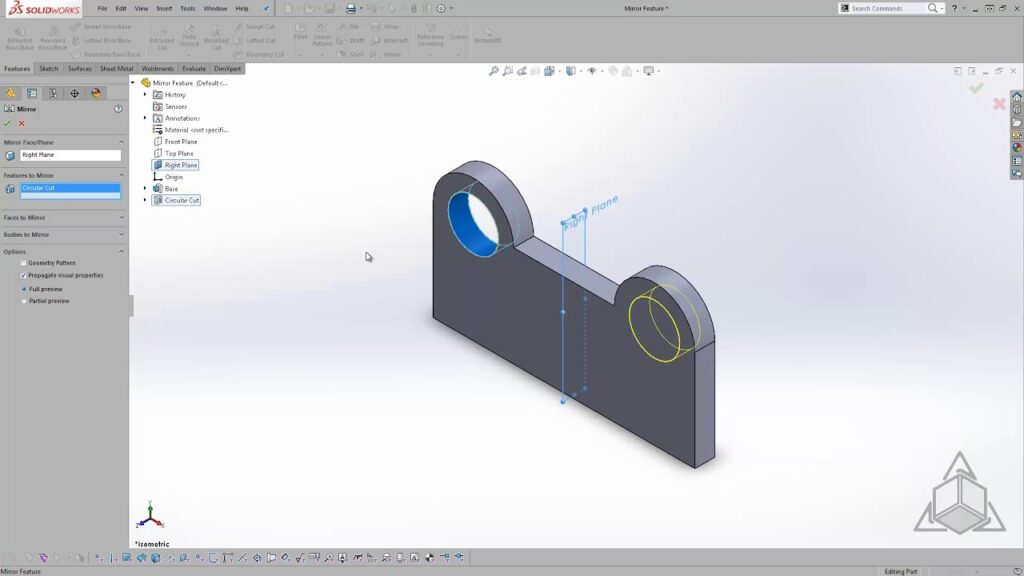
Understanding Feature Mirroring in SolidWorks: Feature mirroring in SolidWorks involves duplicating a feature or set of features across a defined plane or axis to create a symmetrical geometry. Mirroring is commonly used to streamline design workflows, achieve balance and consistency, and reduce modeling time. Before delving into the specifics of mirroring features, it’s crucial to grasp some foundational concepts:
- Sketching and Features:
- Sketching forms the foundation of design in SolidWorks, allowing users to create 2D profiles that define the geometry of parts and features. Features are built upon sketches and represent operations such as extrusions, cuts, fillets, and more.
- Mirror Plane or Axis:
- The mirror plane or axis is a reference plane or line across which features are mirrored in SolidWorks. Users can select existing planes or axes within the model or create custom reference geometry as mirror entities.
- Mirrored Features:
- Mirrored features are duplicates of original features created by the mirroring operation. These features retain the same dimensions, parameters, and relationships as the original features but are positioned symmetrically across the mirror plane or axis.
Mirroring Features in SolidWorks: SolidWorks offers multiple methods for mirroring features, each suited to different design requirements and preferences. Let’s explore the essential tools and techniques for mirroring features:
- Mirror Feature:
- The Mirror Feature command is the primary method for mirroring features in SolidWorks. Users can access the Mirror Feature command from the Insert menu or the right-click context menu and select the features to be mirrored and the mirror plane or axis. SolidWorks then creates mirrored versions of the selected features across the specified reference.
- Mirror Part:
- The Mirror Part command allows users to create a mirrored copy of an entire part or assembly in SolidWorks. Users can access the Mirror Part command from the Insert menu or the right-click context menu and specify the mirror plane or axis. SolidWorks then creates a mirrored instance of the part or assembly across the reference.
- Mirror Components:
- The Mirror Components command is similar to Mirror Part but specifically designed for mirroring components within an assembly in SolidWorks. Users can select individual components or entire subassemblies to be mirrored and specify the mirror plane or axis. SolidWorks then creates mirrored instances of the selected components across the reference.
Advanced Mirroring Techniques: In addition to basic mirroring tools, SolidWorks offers advanced techniques to enhance mirroring workflows and achieve precise design objectives:
- Pattern Driven Component Pattern:
- Pattern Driven Component Pattern allows users to mirror components in an assembly based on a specified pattern or path. This method is useful for creating symmetrical arrays of components along curved or irregular trajectories.
- Dynamic Mirror:
- SolidWorks provides a Dynamic Mirror tool that allows users to preview and adjust mirrored features interactively in real-time. Users can dynamically manipulate the mirror plane or axis and observe changes to the mirrored geometry instantly.
- Multi-Body Part Modeling:
- In multi-body part modeling, users can create symmetric features by designing only half of the part and then mirroring it across a reference plane or axis. This method streamlines the modeling process and ensures consistency between mirrored features.
Best Practices for Feature Mirroring: To maximize efficiency and maintain design integrity when mirroring features in SolidWorks, it’s essential to adhere to best practices:
- Design Intent:
- Consider the functional requirements and aesthetic preferences of your design when mirroring features. Design with symmetry in mind, ensuring that mirrored features align with design intent and maintain consistency across the model.
- Mirror Plane Selection:
- Carefully select the mirror plane or axis to ensure that mirrored features are positioned correctly and symmetrically relative to the original features. Consider using existing planes or axes within the model or creating custom reference geometry as needed.
- Update and Validation:
- Regularly update and validate mirrored features to ensure that they remain synchronized with changes to the original features. Use tools like the FeatureManager design tree, Design Checker, and Interference Detection to identify and resolve any discrepancies or errors.
- Documentation and Communication:
- Document mirrored features clearly and comprehensively to facilitate collaboration and communication with stakeholders and collaborators. Use annotations, notes, and exploded views to convey design intent and manufacturing requirements effectively.
Conclusion: Feature mirroring is a powerful tool in SolidWorks, enabling engineers and designers to achieve symmetry, efficiency, and balance in their designs. By mastering the tools and techniques for mirroring features, you can enhance your design capabilities, streamline your workflow, and produce high-quality models that meet design requirements and manufacturing standards. Whether you’re a novice or an experienced SolidWorks user, understanding the principles of feature mirroring and applying best practices will elevate your design proficiency and enable you to realize your design visions with precision and efficiency.


