Comprehensive Guide to Creating Chamfers in SolidWorks
Introduction: SolidWorks, a prominent computer-aided design (CAD) software, provides engineers and designers with versatile tools to create precise and detailed 3D models. Among its array of features, chamfers stand out as essential tools for adding beveled edges and smooth transitions to parts, enhancing both aesthetics and functionality. In this comprehensive guide, we’ll explore the intricacies of creating chamfers in SolidWorks, covering fundamental concepts, essential techniques, and advanced strategies to help you master this versatile tool.
Understanding Chamfers in SolidWorks: Chamfers in SolidWorks are features that create beveled edges or corners at specified angles along selected edges of a part. Chamfers serve various purposes, including improving part aesthetics, reducing sharp edges, and providing clearance for mating components. Before delving into the specifics of creating chamfers, it’s crucial to grasp some foundational concepts:
- Sketching:
- Sketching serves as the foundation of design in SolidWorks, allowing users to create 2D profiles that define the geometry of parts and features. Sketch entities such as lines, arcs, circles, and splines are used to create sketch geometry.
- Chamfer Feature:
- The Chamfer feature in SolidWorks enables users to add beveled edges or corners to parts. Users can specify parameters such as distance and angle to control the size and orientation of the chamfer. Chamfers can be applied to individual edges or multiple edges simultaneously.
Creating Chamfers in SolidWorks: SolidWorks offers multiple methods for creating chamfers, each suited to different design requirements and preferences. Let’s explore the essential tools and techniques for generating chamfers:
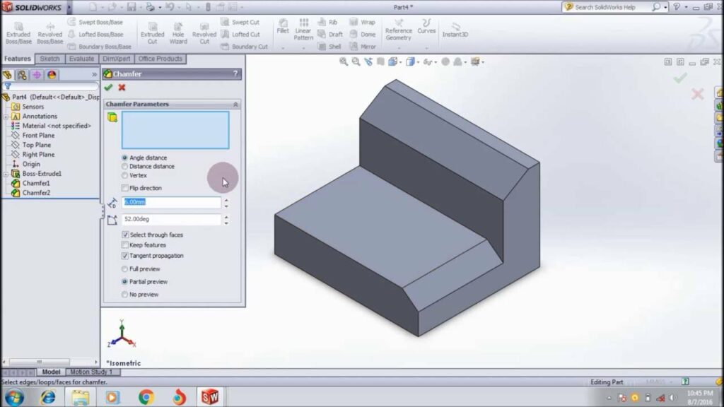
- Chamfer Feature:
- The Chamfer feature is the primary method for adding chamfers to parts in SolidWorks. Users can access the Chamfer feature from the Features tab and select the edges to be chamfered. SolidWorks then applies the specified distance and angle to create the chamfer.
- Edge Fillet:
- While not strictly a chamfer, the Edge Fillet feature can be used to create similar beveled edges by specifying a radius instead of a distance and angle. Users can access the Edge Fillet feature from the Features tab and select edges to apply the fillet. By adjusting the radius, users can achieve chamfer-like effects.
- Sketch-Based Chamfer:
- SolidWorks allows users to create sketch-based chamfers by sketching the desired chamfer profile and extruding or cutting it into the part using the Cut Extrude or Extruded Boss/Base features. Sketch-based chamfers offer greater flexibility and customization options for complex chamfer geometries.
Advanced Chamfering Techniques: In addition to basic chamfering tools, SolidWorks offers advanced techniques to enhance chamfer creation workflows and achieve precise design objectives:
- Variable Chamfers:
- SolidWorks allows users to create chamfers with varying dimensions along a single edge or between multiple edges. Variable chamfers are useful for creating tapered or non-uniform chamfers that adapt to specific design requirements.
- Chamfer Selection:
- SolidWorks provides tools for selecting multiple edges and applying chamfers simultaneously. Users can select edges individually or use selection filters and patterns to expedite the chamfering process, particularly for parts with complex edge configurations.
- ChamferXpert:
- ChamferXpert is a tool in SolidWorks that analyzes part geometry and suggests suitable chamfer sizes and configurations based on specified criteria. Users can access ChamferXpert from the Chamfer PropertyManager and adjust parameters as needed.
Best Practices for Chamfering: To maximize efficiency and maintain design integrity when creating chamfers in SolidWorks, it’s essential to adhere to best practices:
- Design Intent:
- Consider the functional requirements and manufacturing constraints of your design when adding chamfers. Design with future modifications and assembly considerations in mind to ensure the longevity and versatility of your parts.
- Chamfer Size and Angle:
- Select chamfer sizes and angles that are appropriate for your design objectives and manufacturing capabilities. Consider factors such as part function, aesthetic preferences, and clearance requirements when determining chamfer dimensions.
- Edge Selection:
- Carefully select edges for chamfering to ensure that the resulting chamfers meet design intent and aesthetic preferences. Prioritize critical edges for chamfering and avoid excessive chamfering that may compromise part functionality or structural integrity.
- Testing and Validation:
- Regularly test and validate chamfered parts to ensure that they meet design requirements and performance expectations. Use tools like interference detection and simulation to identify potential issues and optimize the design accordingly.
Conclusion: Chamfers are indispensable tools in SolidWorks, offering a versatile method for adding beveled edges and smooth transitions to parts. By mastering the tools and techniques for creating chamfers, you can enhance your design capabilities, streamline your workflow, and produce high-quality models that meet design requirements and manufacturing standards. Whether you’re a novice or an experienced SolidWorks user, understanding the principles of chamfering and applying best practices will elevate your design proficiency and enable you to realize your design visions with precision and elegance.