How to Label Wires and Components in Autodesk Electrical

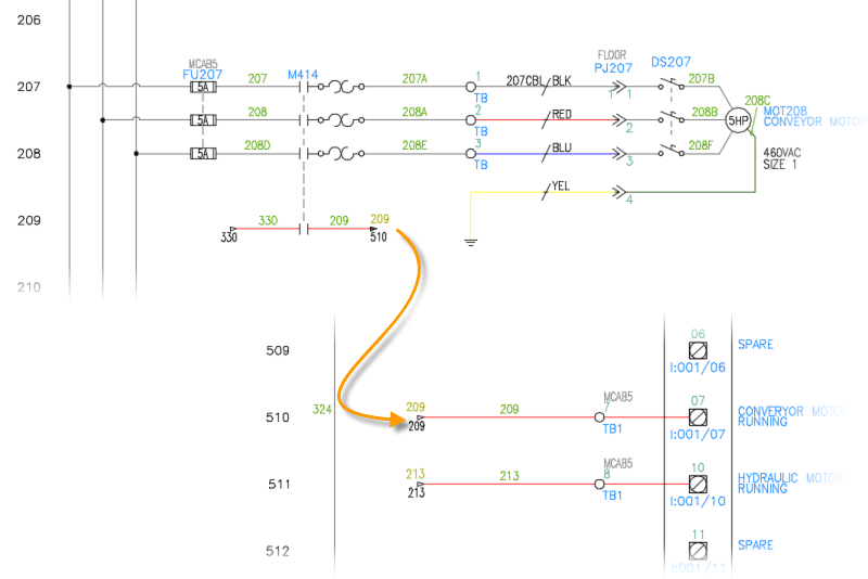
Labeling wires and components in Autodesk Electrical is a crucial step in creating clear and comprehensible schematic drawings. Proper labeling ensures accurate communication of design intent, facilitates troubleshooting and maintenance, and enhances overall efficiency in electrical design projects. In this extensive guide, we’ll explore the process of labeling wires and components in Autodesk Electrical, providing detailed instructions, best practices, and tips to help you create professional-quality schematics.
1. Understanding the Importance of Labeling
Before diving into the labeling process, it’s essential to understand why labeling is crucial in electrical design.
Clarity and Communication
- Clear Identification: Labels provide clear identification of wires and components, reducing confusion and ensuring accurate interpretation of schematic drawings.
- Effective Communication: Proper labeling enables effective communication among designers, engineers, technicians, and other stakeholders involved in the project.
Maintenance and Troubleshooting
- Maintenance Efficiency: Well-labeled schematics streamline maintenance tasks by providing quick access to information about components and connections.
- Troubleshooting Support: Labels aid in troubleshooting electrical systems by facilitating the identification of specific wires, components, and their functions.
Compliance and Standards
- Regulatory Compliance: Labels help ensure compliance with industry standards and regulatory requirements for electrical installations and equipment.
- Standardization: Consistent labeling practices promote standardization across projects, enhancing efficiency and reducing errors.
2. Labeling Wires in Autodesk Electrical
Labeling wires accurately is essential for ensuring clarity and consistency within schematic drawings.
Step 1: Access Wire Labeling Tools
- Wire Labeling Toolbar: Navigate to the wire labeling toolbar in Autodesk Electrical to access wire labeling tools and options.
Step 2: Configure Labeling Settings
- Label Format: Choose the desired format for wire labels, such as alphanumeric codes, numeric sequences, or custom labels.
- Automatic Numbering: Enable automatic numbering to assign unique labels to wires automatically based on predefined settings.
Step 3: Apply Labels to Wires
- Select Wires: Click on individual wire segments or select multiple wires to apply labels.
- Labeling Tool: Use the wire labeling tool from the toolbar to apply labels to selected wires.
Step 4: Customize Label Properties
- Label Format: Customize label properties such as font size, style, color, and alignment to ensure readability and consistency.
- Positioning: Adjust the position of labels relative to wire segments to optimize clarity and visual presentation.
Step 5: Review and Validate Labels
- Visual Inspection: Conduct a visual inspection of labeled wires to ensure accuracy and consistency in labeling.
- Validation Process: Validate wire labels against design specifications or requirements to ensure compliance and accuracy.
3. Labeling Components in Autodesk Electrical
Labeling components accurately is equally important for conveying information effectively within schematic drawings.
Step 6: Access Component Labeling Options
- Component Labeling Toolbar: Access the component labeling toolbar in Autodesk Electrical to explore labeling options and tools.
Step 7: Configure Component Labeling Settings
- Label Format: Choose the appropriate format for component labels, such as alphanumeric codes, symbols, or custom labels.
- Automatic Labeling: Enable automatic labeling to assign labels to components automatically based on predefined settings.
Step 8: Apply Labels to Components
- Select Components: Click on individual components or select multiple components to apply labels.
- Labeling Tool: Utilize the component labeling tool from the toolbar to apply labels to selected components.
Step 9: Customize Label Properties
- Label Format: Customize label properties such as font size, style, color, and alignment to ensure consistency and clarity.
- Positioning: Adjust the position of labels relative to components to optimize visibility and readability.
Step 10: Review and Validate Labels
- Visual Inspection: Review labeled components within schematic drawings to verify accuracy and completeness of labeling.
- Validation Process: Validate component labels against design specifications or requirements to ensure alignment and compliance.
4. Best Practices for Labeling in Autodesk Electrical
To ensure effective labeling in Autodesk Electrical, consider the following best practices:
Consistent Naming Conventions
- Standardized Labels: Establish consistent naming conventions for wires and components to ensure uniformity and clarity across schematic drawings.
- Descriptive Labels: Use descriptive labels that convey relevant information about wires and components, such as function, location, or specifications.
Automated Labeling
- Utilize Automation: Take advantage of Autodesk Electrical’s automation features to streamline the labeling process and minimize manual effort.
- Automation Settings: Configure automation settings to generate labels automatically based on predefined rules and criteria.
Clear Presentation
- Optimize Visibility: Ensure labels are positioned prominently and clearly visible within schematic drawings to facilitate quick identification and reference.
- Avoid Clutter: Avoid overcrowding schematic drawings with excessive labels by prioritizing essential information and maintaining a clean layout.
Regular Review and Maintenance
- Periodic Review: Schedule regular reviews of labeled wires and components to identify any inconsistencies, errors, or omissions.
- Update as Needed: Update labels as needed to reflect changes or revisions in the design, ensuring accuracy and alignment with project requirements.
5. Collaboration and Documentation
Effective collaboration and documentation practices support successful labeling in Autodesk Electrical.
Collaborative Environment
- Team Communication: Foster open communication and collaboration among team members to ensure consistent labeling practices and alignment with project objectives.
- Feedback Mechanism: Establish a feedback mechanism to gather input and suggestions for improving labeling processes and standards.
Comprehensive Documentation
- Labeling Guidelines: Document labeling guidelines and standards to provide clear instructions and reference materials for designers and stakeholders.
- Documentation Repository: Maintain a centralized repository of labeling documentation, templates, and resources for easy access and reference.
Conclusion
Labeling wires and components in Autodesk Electrical is a critical aspect of creating clear, comprehensible schematic drawings. By following the steps outlined in this guide and adhering to best practices, you can ensure accurate, consistent, and effective labeling within your electrical design projects. Whether you’re working on simple circuits or complex systems, mastering the labeling process will enable you to convey information clearly, facilitate maintenance and troubleshooting, and achieve superior results in your designs.


