How to Create and Use Wire Layers in Autodesk Electrical
Wire layers in Autodesk Electrical play a crucial role in organizing and managing the wiring within schematic drawings. By utilizing wire layers effectively, designers can maintain clarity, consistency, and efficiency in their electrical designs. In this comprehensive guide, we’ll explore the process of creating and using wire layers in Autodesk Electrical, providing detailed instructions and best practices to help you optimize your schematic drawings.
1. Understanding Wire Layers in Autodesk Electrical
Wire layers in Autodesk Electrical are virtual layers that allow designers to categorize and differentiate between different types of wiring within schematic drawings. Each wire layer can have unique properties such as color, line type, and visibility settings, enabling designers to customize the appearance and behavior of wires based on their function or purpose.
2. Creating Wire Layers
Before incorporating wire layers into your schematic drawings, you’ll need to create the desired wire layers within Autodesk Electrical.
Step 1: Open Layer Manager
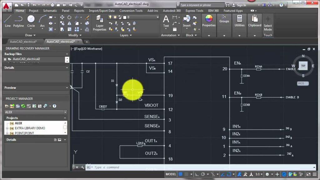
- Access Layer Manager: Click on the Layer Manager icon located in the main toolbar of Autodesk Electrical to open the Layer Manager window.
Step 2: Add New Layer
- Create New Layer: In the Layer Manager window, click on the ‘Add New Layer’ button to create a new wire layer.
- Specify Layer Properties: Enter a name for the new layer and configure its properties such as color, line type, and visibility settings.
Step 3: Repeat for Additional Layers
- Multiple Layers: If you require multiple wire layers for different types of wiring (e.g., power, control, signal), repeat the process to create additional layers as needed.
- Customization: Customize the properties of each layer according to its specific function or purpose.
3. Assigning Wire Layers to Components
After creating wire layers, you’ll need to assign the appropriate wire layers to components within your schematic drawings.
Step 4: Select Component
- Component Selection: Click on the component to select it within the schematic drawing.
Step 5: Access Properties
- Properties Dialog: Right-click on the selected component and choose the ‘Properties’ option to access its properties dialog box.
Step 6: Assign Wire Layer
- Wire Layer Assignment: In the properties dialog box, locate the option to assign a wire layer to the component.
- Select Layer: Choose the appropriate wire layer from the dropdown menu to assign it to the component.
4. Routing Wires on Specific Layers
Once wire layers are assigned to components, you can route wires on specific layers within your schematic drawings.
Step 7: Select Wiring Tool
- Wiring Toolbar: Access the wiring toolbar in Autodesk Electrical and choose the desired wiring tool (e.g., straight wire, curved wire).
Step 8: Enable Layer Control
- Layer Control: Locate the layer control options within the wiring toolbar and enable the option to specify the wire layer for routing.
Step 9: Route Wires on Designated Layer
- Layer Selection: Select the desired wire layer from the layer control options before routing wires between components.
- Routing Process: Proceed with routing wires as usual, ensuring that wires are routed on the designated layer.
5. Adjusting Layer Visibility
To maintain clarity and organization within schematic drawings, you can adjust the visibility of wire layers as needed.
Step 10: Open Layer Manager
- Access Layer Manager: Return to the Layer Manager window by clicking on the Layer Manager icon in the main toolbar.
Step 11: Toggle Visibility
- Visibility Settings: Use the visibility toggles next to each wire layer to control whether the layer is visible or hidden within the schematic drawing.
Step 12: Organize Display
- Layer Order: Adjust the order of wire layers within the Layer Manager to control their display priority within the schematic drawing.
- Grouping: Group related wire layers together within the Layer Manager to streamline visibility management.
6. Benefits of Using Wire Layers
Incorporating wire layers into your schematic drawings offers several benefits for electrical design projects.
Clarity and Organization
- Visual Differentiation: Wire layers allow for visual differentiation between different types of wiring, enhancing clarity and comprehension within schematic drawings.
- Structured Layout: Organizing wiring on separate layers enables designers to create a structured and organized layout, reducing clutter and confusion.
Flexibility and Customization
- Customization Options: Wire layers offer flexibility in customizing the appearance and behavior of wiring based on specific project requirements or preferences.
- Adaptability: Designers can easily adjust wire layers and properties as needed throughout the design process, accommodating changes or revisions efficiently.
Error Prevention and Troubleshooting
- Error Identification: By categorizing wiring on separate layers, designers can quickly identify and troubleshoot errors or discrepancies within schematic drawings.
- Enhanced Collaboration: Clear organization and visibility of wire layers facilitate collaboration among team members, fostering effective communication and problem-solving.
7. Best Practices for Using Wire Layers
To maximize the effectiveness of wire layers in Autodesk Electrical, consider the following best practices:
Consistent Naming Conventions
- Standardized Names: Establish consistent naming conventions for wire layers to ensure clarity and consistency across schematic drawings.
- Descriptive Labels: Use descriptive labels or abbreviations to clearly indicate the function or purpose of each wire layer.
Clear Documentation
- Layer Documentation: Maintain detailed documentation of wire layers, including their properties, assignments, and usage guidelines.
- Revision History: Keep track of changes or revisions to wire layers to facilitate version control and troubleshooting.
Regular Review and Validation
- Periodic Review: Schedule regular reviews of wire layers within schematic drawings to identify any inconsistencies or errors.
- Validation Process: Validate wire layer assignments and routing against design specifications or requirements to ensure accuracy and compliance.
Training and Collaboration
- Training Programs: Provide training for team members on the use of wire layers and other features within Autodesk Electrical.
- Collaborative Environment: Foster collaboration among team members to share knowledge and best practices for utilizing wire layers effectively.
Conclusion
Incorporating wire layers into schematic drawings in Autodesk Electrical offers numerous benefits for electrical design projects, including enhanced clarity, organization, and flexibility. By following the steps outlined in this guide and adhering to best practices, you can create structured and well-organized schematic drawings that facilitate efficient design processes and error-free construction. Whether you’re working on simple circuits or complex systems, mastering the use of wire layers will enable you to optimize your electrical designs and achieve superior results.