How to Import CAD Geometry into ANSYS
Importing CAD geometry into ANSYS is a fundamental step in preparing models for simulation and analysis. ANSYS supports various CAD formats, allowing engineers and designers to seamlessly transfer geometric data from CAD software to ANSYS for finite element analysis (FEA), computational fluid dynamics (CFD), electromagnetic simulations, and more. This comprehensive guide will walk you through the step-by-step process of importing CAD geometry into ANSYS, covering different methods, supported file formats, best practices, and troubleshooting tips.
Table of Contents
- Introduction to CAD Geometry Import
- Supported CAD Formats in ANSYS
- Methods for Importing CAD Geometry into ANSYS
- Preparing CAD Geometry for Import
- Troubleshooting CAD Import Issues
- Best Practices for CAD Geometry Import
- Conclusion
1. Introduction to CAD Geometry Import
CAD geometry import is the process of transferring geometric models from CAD software packages like SolidWorks, CATIA, AutoCAD, Pro/ENGINEER, and others into ANSYS for simulation and analysis. This capability is essential for engineers and designers to leverage existing design data for virtual prototyping, optimization, and validation using ANSYS simulation tools.
2. Supported CAD Formats in ANSYS
ANSYS supports a wide range of CAD formats for geometry import. Some of the commonly supported formats include:
- Parasolid (*.x_t, *.x_b): Widely used for solid modeling, compatible with most CAD systems.
- STEP (*.stp, *.step): ISO standard for exchanging CAD data between different systems.
- IGES (*.igs, *.iges): Initial Graphics Exchange Specification, older but still widely used for geometry exchange.
- ACIS (*.sat, *.sab): Used for 3D solid modeling, interoperable with many CAD systems.
- SolidWorks (*.sldprt, *.sldasm): Native file formats of SolidWorks for parts and assemblies.
- CATIA (*.CATPart, *.CATProduct): Native formats of CATIA for parts and assemblies.
- AutoCAD (*.dwg, *.dxf): Native formats of AutoCAD for 2D and 3D drawings.
3. Methods for Importing CAD Geometry into ANSYS
- Direct Import in ANSYS Workbench:
- Launch ANSYS Workbench and start a new project.
- Use the Geometry cell to import CAD files directly into the project schematic.
- Navigate to
Geometry>Import Geometryand select the desired CAD file format.
- Using ANSYS Mechanical APDL:
- Launch ANSYS Mechanical APDL (Classic) if you prefer using command-based interface.
- Use commands like
/PREP7>FILE>IGESIN,STEPIN, etc., to import IGES, STEP, or other formats.
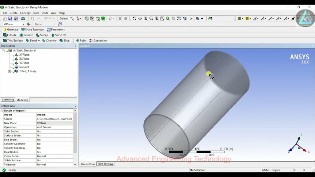
- ANSYS DesignModeler:
- Start ANSYS DesignModeler from within ANSYS Workbench.
- Import CAD files directly into DesignModeler for preprocessing and model simplification.
- ANSYS SpaceClaim:
- Use ANSYS SpaceClaim for direct CAD manipulation and geometry preparation.
- Import CAD files, repair geometry, simplify models, and prepare for meshing.
4. Preparing CAD Geometry for Import
- Check CAD File Integrity:
- Ensure the CAD file is complete and does not contain errors or missing components.
- Validate the CAD model in the native CAD software before exporting to ANSYS.
- Simplify Geometry:
- Remove unnecessary features, small details, and internal components that are not essential for analysis.
- Simplify assemblies to reduce computational overhead and improve mesh quality.
- Verify Units and Scales:
- Confirm that the CAD model uses the correct units (e.g., millimeters, inches) consistent with the intended analysis in ANSYS.
- Scale the geometry if necessary to match the desired dimensions in ANSYS.
5. Troubleshooting CAD Import Issues
- Unsupported Features or Formats:
- Check if ANSYS supports the specific CAD format and version you are trying to import.
- Convert CAD files to a compatible format if necessary using native CAD software or third-party converters.
- Geometry Repair:
- Use ANSYS DesignModeler or SpaceClaim to repair geometry errors such as gaps, overlaps, or invalid entities.
- Inspect and clean up CAD geometry before importing into ANSYS for simulation.
- Memory and Performance Issues:
- Large CAD assemblies may require additional memory and computational resources.
- Optimize CAD models for efficient handling in ANSYS by simplifying geometry and reducing complexity.
6. Best Practices for CAD Geometry Import
- Use Native CAD Formats:
- Whenever possible, import CAD geometry using native file formats (e.g., Parasolid for SolidWorks) to retain design intent and feature history.
- Organize Geometry Hierarchy:
- Maintain a structured assembly hierarchy to facilitate easier manipulation and boundary condition assignment in ANSYS.
- Document CAD Version:
- Document the CAD software version used to create the geometry to ensure compatibility with ANSYS.
7. Conclusion
Importing CAD geometry into ANSYS is a critical initial step in preparing models for simulation and analysis across various engineering disciplines. By following the methods, best practices, and troubleshooting tips outlined in this guide, engineers and designers can effectively transfer CAD data into ANSYS, ensuring accurate representation of geometrical features and efficient setup for subsequent simulations. ANSYS’s robust capabilities for CAD import, coupled with its powerful simulation tools, enable users to leverage existing design data for virtual prototyping, optimization, and validation, driving innovation and engineering excellence in product development and research endeavors.