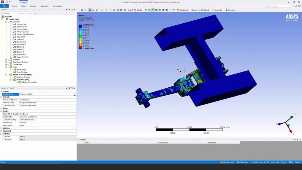
How to Create a Finite Element Mesh in ANSYS

Creating a finite element mesh is a critical step in finite element analysis (FEA) using ANSYS software. The quality of the mesh directly influences the accuracy and reliability of simulation results. ANSYS provides powerful tools and techniques for generating meshes that accurately represent the geometry of structures or components, ensuring optimal simulation performance. This comprehensive guide will walk you through the step-by-step process of creating a finite element mesh in ANSYS, covering meshing fundamentals, geometry preparation, mesh generation techniques, mesh quality considerations, and advanced meshing capabilities.
Table of Contents
- Introduction to Finite Element Meshing
- Geometry Preparation for Meshing
- Mesh Generation Techniques in ANSYS
- Mesh Quality Considerations
- Advanced Meshing Techniques
- Troubleshooting and Common Issues
- Conclusion
1. Introduction to Finite Element Meshing
Finite element meshing is the process of dividing a complex geometry into smaller, simpler elements (such as triangles or quadrilaterals in 2D, and tetrahedrons or hexahedrons in 3D) to discretize the domain for analysis. The mesh serves as a numerical representation of the physical structure or component, allowing engineers to simulate and analyze its behavior under various conditions. The key objectives of meshing include:
- Ensuring geometric accuracy and fidelity.
- Achieving sufficient mesh resolution to capture details and variations in structural response.
- Optimizing computational efficiency without compromising simulation accuracy.
2. Geometry Preparation for Meshing
- Import Geometry:
- Import the CAD geometry of the structure or component into ANSYS.
- Supported formats include STEP, IGES, Parasolid, and native CAD formats.
- Geometry Cleanup:
- Ensure the geometry is clean and free from any gaps, overlaps, or small features that may affect mesh quality.
- Use ANSYS DesignModeler or SpaceClaim for geometry cleanup if necessary.
- Simplify Geometry:
- Simplify complex features or assemblies to reduce computational resources and improve mesh quality.
3. Mesh Generation Techniques in ANSYS
- Automatic Meshing:
- Use ANSYS Meshing (also known as Workbench Meshing) for automatic mesh generation.
- Define sizing controls and mesh parameters to guide the software in generating the mesh.
- Manual Meshing:
- For more control over mesh quality and distribution, manually create nodes and elements using ANSYS Mechanical APDL.
- Define element types (e.g., tetrahedral, hexahedral) and specify connectivity between nodes.
- Mesh Controls:
- Apply sizing controls to refine or coarsen the mesh locally in regions of interest.
- Use curvature-based sizing, proximity sizing, and inflation layers for boundary layer meshing in fluid domains.
4. Mesh Quality Considerations
- Aspect Ratio:
- Ensure elements have reasonable aspect ratios (length/width) to prevent skewness and numerical inaccuracies.
- Aim for elements with aspect ratios close to 1 to maintain mesh quality.
- Element Shape and Size:
- Use smaller elements in regions with high stress gradients or geometric complexities to capture accurate results.
- Avoid overly large or overly small elements that can lead to interpolation errors or excessive computational costs.
- Element Quality Metrics:
- Check element quality metrics such as skewness, Jacobian ratio, and aspect ratio using ANSYS Meshing tools.
- Target minimum quality thresholds to ensure reliable simulation results.
5. Advanced Meshing Techniques
- Mesh Refinement:
- Perform mesh refinement studies to assess the sensitivity of results to changes in mesh density.
- Use adaptive meshing techniques to automatically refine the mesh based on solution criteria (e.g., error estimation).
- Boundary Layer Meshing:
- Generate boundary layer meshes near solid boundaries in fluid flow simulations to resolve boundary layer effects.
- Use inflation layers and prism elements to capture near-wall flow dynamics accurately.
- Mesh Morphing and Optimization:
- Apply mesh morphing techniques to adjust mesh density and distribution based on structural deformations or design changes.
- Optimize mesh quality iteratively to improve convergence and solution accuracy.
6. Troubleshooting and Common Issues
- Mesh Convergence:
- Address mesh convergence issues by refining the mesh in critical regions or adjusting solver settings.
- Ensure adequate mesh resolution to capture localized phenomena without excessive computational cost.
- Geometry Compatibility:
- Verify compatibility between CAD geometry and meshing algorithms to prevent geometry-related errors.
- Check for invalid geometrical entities or features that may hinder mesh generation.
- Mesh Distortions:
- Identify and resolve mesh distortions or irregularities that may affect element quality and solution stability.
- Use mesh diagnostics and visualization tools to inspect and debug meshing problems.
7. Conclusion
Creating a finite element mesh in ANSYS is a foundational step in performing accurate and reliable simulations for engineering analysis. By following the guidelines and techniques outlined in this guide, engineers and analysts can effectively prepare, generate, and validate meshes that capture the geometric complexity and physical behavior of structures or components. ANSYS offers versatile tools and capabilities for meshing, enabling users to optimize designs, evaluate performance, and make informed engineering decisions across diverse industries. Understanding the nuances of meshing fundamentals, mesh quality considerations, and advanced meshing techniques empowers engineers to achieve robust simulation results and drive innovation in product development and design optimization.


