How to connect front panel headers
Introduction to Front Panel Headers
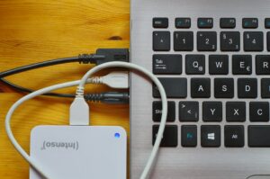
Front panel headers consist of various connectors and pins located on the front panel of your computer case. These include power buttons, reset buttons, LED indicators for power and activity, USB ports, and audio jacks. Connecting these headers correctly to the motherboard ensures that these components operate as intended.
Preparation
Before you start connecting front panel headers, gather the necessary tools and information:
- Tools Needed:
- Small flathead screwdriver (optional, for manipulating jumper caps)
- Flashlight or adequate lighting to see the motherboard layout and header labels clearly.
- Motherboard Manual:
- Refer to the motherboard manual to identify the specific locations and functions of each front panel header pin. Motherboards may vary in layout and labeling.
- Case Manual (if available):
- Some computer cases provide a manual detailing the layout and functions of front panel connectors, which can be helpful for first-time builders.
- Safety Precautions:
- Power off your computer and unplug it from the power source before handling any internal components.
- Ground yourself by touching a metal part of the case to discharge any static electricity and prevent damage to sensitive electronics.
Step-by-Step Guide to Connect Front Panel Headers
Step 1: Identify Front Panel Header Pins
- Locate Front Panel Header Pins:
- Identify the front panel header pins on your motherboard. These are usually located along one edge or corner of the motherboard, often labeled with abbreviations for each function (e.g., PWR_SW for power switch, HDD_LED for hard drive LED).
- Refer to Motherboard Manual:
- Consult the motherboard manual to locate the exact position and function of each pin on the front panel header. The manual provides a detailed diagram of the motherboard layout and pin configurations.
Step 2: Prepare Front Panel Cables
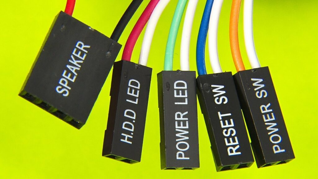
- Separate Front Panel Cables:
- Separate individual cables for power/reset switches, LED indicators (power and HDD), USB ports, and audio jacks from the front panel. Each cable typically terminates in a connector or set of pins.
- Identify Positive and Negative Leads:
- For LED connectors (power LED, HDD LED), identify the positive (+) and negative (-) leads. The positive lead is usually labeled with a “+” or a colored wire (typically white or colored) and connects to the corresponding pin on the motherboard.
Step 3: Connect Front Panel Headers to Motherboard
- Align and Connect Pins:
- Align each front panel connector with its corresponding header pin on the motherboard, ensuring correct orientation. The connectors are often labeled for easy identification.
- Secure Connectors:
- Gently press each connector onto its respective header pin. Ensure a snug fit without applying excessive force. Some connectors may have locking mechanisms to hold them in place.
- Double-Check Connections:
- Double-check each connection to ensure that all pins are securely connected and none are loose or misaligned. Loose connections can cause components like power buttons or LEDs to malfunction.
Step 4: Test Front Panel Functionality
- Power On Your Computer:
- Once all front panel connectors are securely connected, plug your computer back into the power source and power it on.
- Test Power and Reset Buttons:
- Press the power button to ensure that your computer powers on correctly. Press the reset button to verify it resets the system when pressed.
- Check LED Indicators:
- Observe the power LED and HDD LED indicators to ensure they light up and indicate activity when appropriate.
- Test USB Ports and Audio Jacks (if applicable):
- Plug in USB devices to verify that front panel USB ports function correctly. Connect headphones or speakers to audio jacks to ensure audio output is working.
Step 5: Cable Management
- Organize Front Panel Cables:
- Bundle and route front panel cables neatly using cable ties or Velcro straps. Secure cables along designated cable management channels or tie-down points inside the case to prevent them from obstructing airflow or tangling with other components.
- Close Your Computer Case:
- Once all front panel headers are connected and tested, carefully close the computer case and secure it with screws or latches. Ensure all screws are tightened to prevent vibrations.
Troubleshooting
If your front panel components do not function correctly after connecting headers, consider the following troubleshooting steps:
- Check Connections: Verify each connection for proper alignment and secure attachment to the motherboard headers.
- Review Motherboard Manual: Double-check the pin configurations and labels in the motherboard manual to ensure correct placement.
- Test Individual Components: Test each front panel component individually (e.g., power switch, LEDs) to identify specific issues.
Conclusion
Connecting front panel headers is a crucial step in building or maintaining a computer system. By following this step-by-step guide and taking necessary precautions, you can ensure that your front panel buttons, LEDs, USB ports, and audio jacks function correctly, providing convenient access and control for your computing needs.
Always refer to the specific instructions provided by your motherboard and computer case manufacturers for detailed guidance and recommendations specific to your hardware.