Comprehensive Guide to Shelling Parts in SolidWorks
Introduction: SolidWorks, a leading computer-aided design (CAD) software, offers engineers and designers a robust set of tools for creating precise and intricate 3D models. One essential feature in SolidWorks is the shell command, which hollows out solid parts to create thin-walled structures. Shelling is a fundamental operation used in various industries, including automotive, aerospace, consumer goods, and more. In this comprehensive guide, we’ll explore the intricacies of shelling parts in SolidWorks, covering fundamental concepts, essential techniques, and advanced strategies to help you master this versatile tool.
Understanding Shelling in SolidWorks: Shelling in SolidWorks involves removing material from the interior of a solid part, leaving behind a thin-walled structure with specified thickness. This process is commonly used to create hollow components such as enclosures, housings, and shells for molded parts. Before delving into the specifics of shelling, it’s crucial to grasp some foundational concepts:
- Solid Bodies:
- In SolidWorks, parts are composed of solid bodies, which represent continuous volumes of material. Solid bodies can be created through features such as extrusions, revolves, and sweeps.
- Shell Thickness:
- The shell thickness is the distance between the original exterior surface of the part and the new inner surface created during the shelling process. Users can specify the shell thickness based on design requirements and manufacturing considerations.
- Shell Direction:
- The shell direction determines the direction in which material is removed from the part to create the hollow interior. Users can specify the shell direction as inward or outward, depending on the desired configuration of the hollow structure.
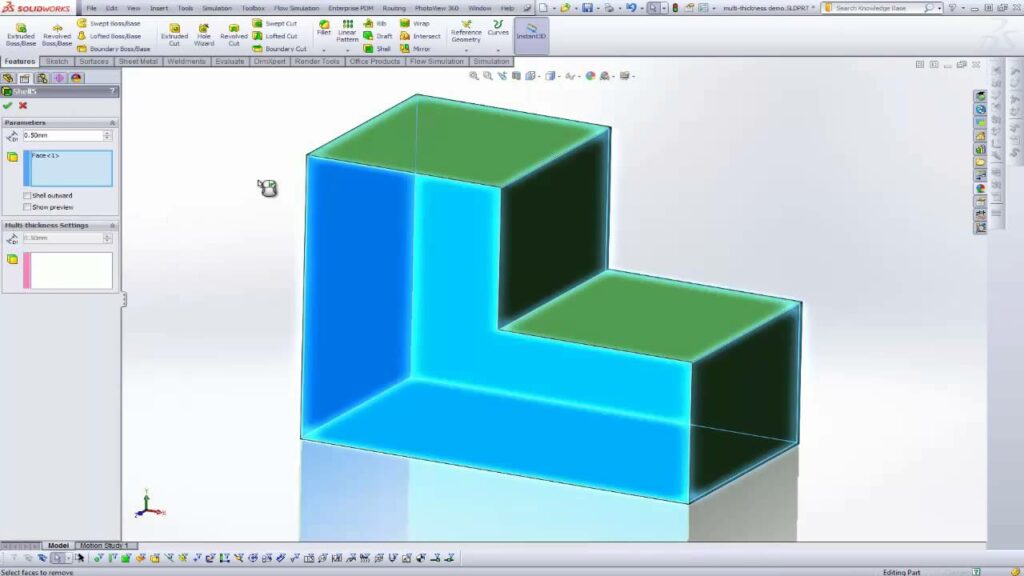
Shelling Parts in SolidWorks: SolidWorks offers a straightforward method for shelling parts, allowing users to hollow out solid geometry with ease. Let’s explore the essential steps for shelling parts:
- Select the Part:
- Begin by selecting the part or assembly in SolidWorks that you want to shell. The part should be a solid body with a closed volume, such as a solid block, extruded shape, or imported geometry.
- Access the Shell Command:
- Once the part is selected, navigate to the Insert menu or the right-click context menu and choose the Shell command. Alternatively, you can access the Shell command from the Features tab in the Command Manager.
- Define Shell Parameters:
- After activating the Shell command, SolidWorks prompts you to specify the parameters for the shell operation. First, select the faces or features that define the boundaries of the shell. Then, specify the shell thickness and direction.
- Preview and Confirm:
- SolidWorks provides a preview of the shelled part, allowing you to visualize the hollow structure before confirming the operation. Review the preview to ensure that the shell parameters are configured correctly, then click OK to apply the shell.
Advanced Shelling Techniques: In addition to basic shelling tools, SolidWorks offers advanced techniques to enhance shelling workflows and achieve precise design objectives:
- Multi-Thickness Shells:
- SolidWorks allows users to create shells with variable thicknesses using the Multi-Thickness Shell command. This feature is useful for creating parts with varying wall thicknesses or localized reinforcement.
- Shell Cutouts:
- Users can create cutouts or openings in shelled parts using the Shell Cutout command. This tool enables users to remove material from specific regions of the shell, leaving behind customized voids or access points.
- Non-Uniform Shells:
- SolidWorks provides tools for creating non-uniform shells with varying thicknesses and profiles. Users can sketch custom profiles or trajectories to define the shape and thickness distribution of the shell, enabling complex geometries such as tapered or contoured shells.
Best Practices for Shelling: To maximize efficiency and maintain design integrity when shelling parts in SolidWorks, it’s essential to adhere to best practices:
- Design Intent:
- Consider the functional requirements, aesthetic preferences, and manufacturing constraints of your design when shelling parts. Design with symmetry in mind, ensuring that the hollow structure aligns with design intent and maintains structural integrity.
- Wall Thickness:
- Select an appropriate wall thickness for the shell based on material properties, part function, and manufacturing considerations. Consider factors such as stiffness, weight, and cost when determining the optimal shell thickness.
- Internal Features:
- Account for internal features such as ribs, bosses, and mounting points when shelling parts. Ensure that these features are properly positioned and oriented relative to the hollow structure to maintain functionality and compatibility with assembly components.
- Validation and Testing:
- Regularly test and validate shelled parts to ensure that they meet design requirements and performance expectations. Use tools like simulation, physical testing, and prototyping to verify structural integrity, material strength, and functional compatibility.
Conclusion: Shelling is a powerful tool in SolidWorks, enabling engineers and designers to create hollow components with ease and precision. By mastering the tools and techniques for shelling parts, you can enhance your design capabilities, streamline your workflow, and produce high-quality models that meet design requirements and manufacturing standards. Whether you’re a novice or an experienced SolidWorks user, understanding the principles of shelling and applying best practices will elevate your design proficiency and enable you to realize your design visions with precision and efficiency.